

A “12 V,” “24 V” or “48 V” vehicle label is not a complete MLV requirement. The local rail may see charging tolerance, jump start, switching events, conducted transients, ground offset and temperatures far beyond its nominal value.
Do not publish a universal rail-to-part table. Build the requirement from the actual module, then select an exact automotive/high-energy MLV and its position in a coordinated protection architecture.
Define the Rail and Its States
Record nominal and worst-case continuous voltage, charging/tolerance range, powered/unpowered behavior, jump-start or abnormal-overvoltage duration, source impedance, load current, ambient/board temperature and the protected converter/IC limit.
Distinguish a vehicle bus input from a regulated local rail. A board-level MLV on a secondary rail does not automatically see the same pulse as the vehicle connector, and its lower clamp target does not mean it can absorb the upstream energy.
Set the Voltage and Clamp Window
| Gate | Required evidence | Failure |
|---|---|---|
| Continuous voltage | VDC/VAC basis, tolerance, abnormal duration, temperature derating | Leakage/heating during valid operation |
| Varistor voltage | Min/nom/max and test current | V1mA or V10mA compared as identical |
| Clamp | Vc at exact current, waveform and temperature | Protected-node limit exceeded |
| Pulse/energy | Generator, source impedance, duration, repetition and acceptance | 8/20 µs substituted for load dump |
| Thermal/life | Ambient, board, cooling interval, drift and failure state | One-shot rating treated as mission-profile life |
Use the parameter and test-condition guide. KYOCERA AVX, Eaton and other automotive tables include model-specific Vjump, load-dump energy, current, capacitance and temperature fields; they cannot be combined into a fictional family maximum.
Document edition matters as much as the pulse label. The current KYOCERA AVX TransGuard Automotive Rev 4 document still references ISO 7637-2-2004 and an older pulse basis, while ISO lists ISO 7637-2:2011 as the current edition, last reviewed and confirmed in 2025. Treat the supplier table as exact product-test evidence, not as an unstated claim of compliance with a later standard edition.
Coordinate the Protection Stages
A local MLV may clamp switching noise or residual transient energy after an upstream TVS/MOV. Review source/harness impedance, series resistance or inductor, input capacitor, fuse/current limiting and the converter’s absolute maximum. Confirm that the upstream stage does not leave the local MLV with unsupported energy.
For load dump and other long events, use the dedicated long-pulse protection guide. Never infer long-pulse capability from a short peak-current rating.
Handle 48 V and High Temperature as Exact Scope
Higher-voltage vehicle systems reduce the available margin between valid operation and clamp requirements. High-temperature and VDA-320 claims apply only to the listed order codes, package, termination and supplier scope. KYOCERA AVX VT-series evidence, for example, separates VTA3, VTA7 and specified 48 V-system devices; it is not a blanket claim for every automotive MLV.
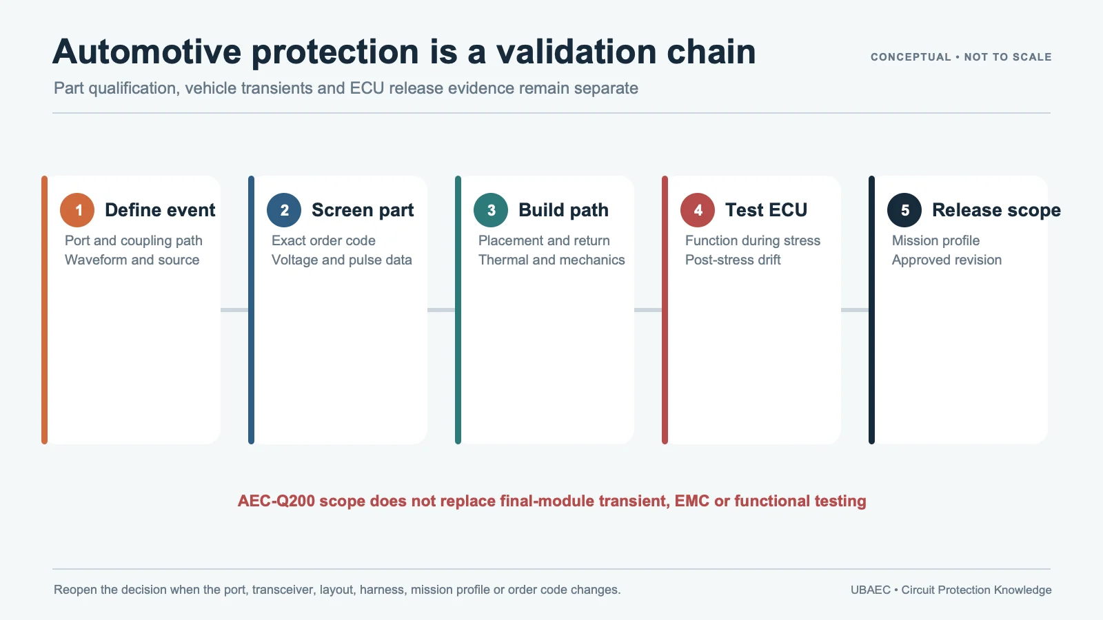
AEC-Q200 does not establish ECU or vehicle compliance. Use the reliability and standards guide and verify the current exact-part declaration.
What Changes Between 12 V, 24 V and 48 V Projects
The higher rail name does not simply scale every device value. Valid operating range, jump-start condition, load-dump network, source impedance, protected converter technology and customer acceptance plan can all change. A device optimized for clamp margin on one rail may have excessive leakage on another, while a high-VDC device can leave too much residual voltage for a lower-voltage IC.
For a 48 V project, confirm whether the source uses a named 48 V-system/VDA-320 order code or merely a component with a similar working voltage. For 12 V or 24 V, do not assume every supplier’s “automotive” family uses the same jump-start duration, load-dump energy or temperature grade. Preserve the original table headings and footnotes.
Approve the Exact Order Code, Not the Family
Record package, termination, VDC, Vvar definition, Vc/current, short-pulse current, energy waveform, WLD/Vjump, capacitance basis, leakage, operating temperature, qualification and lifecycle. Missing fields remain a hold. Distributor stock, a category-page maximum or a neighboring package cannot fill the gap.
The approval statement should identify the rail and module revision, upstream protection, pulse plan and validated operating range. Any change to the source network, fuse, converter, PCB thermal path or MLV alternate reopens the coordination and test decision.
Validation Plan
- Measure worst-case rail and leakage across temperature and operating modes.
- Apply each required automotive pulse with its exact source impedance and repetition.
- Measure MLV current, local-rail clamp and protected-device voltage simultaneously.
- Monitor MLV/PCB temperature and cooling between events.
- Check function, leakage, Vvar, clamp and physical condition after stress.
- Run fuse/current-limit and MLV short/open fault scenarios required by the safety plan.
Apply the MLV selection workflow, review construction against the MLV/MOV boundary, and validate footprint/assembly with the layout guide. An alternate requires the cross-reference method and repeat testing.
Minimum Inquiry Data
- rail location, nominal/worst-case/abnormal voltage and duration;
- source impedance, pulse generators, repetition and pass criteria;
- converter/IC limit, input capacitance and upstream protection;
- temperature, airflow/PCB copper, package, qualification and lifecycle;
- fault-current, fuse/current limiting and required failure containment.
Summary
Automotive local-rail protection is selected from the actual voltage window, pulse network, energy, temperature and coordinated stages—not the rail name. Approve only the exact order code after measured module and fault validation.
Use the MLV Technical Resources & Datasheet Library, return to the MLV Knowledge Map, or ask UBAEC with the rail and test plan.
Continue Reading
- Automotive Load Dump, Jump Start and Long-Pulse MLV Protection
- MLV Datasheet Parameters and Test Conditions
- MLV Reliability, Standards and Failure Modes
- How to Select an MLV: A Practical Engineering Workflow
Official Technical References
The following first-party, standards-organization or publisher records support the technical boundaries used in this article. Always verify the current revision and the exact product scope before design release.
- TransGuard Automotive Series multilayer varistors datasheet
- AMLV automotive grade multilayer varistor datasheet
- ISO 7637-2:2011 – Road vehicles – Electrical disturbances from conduction and coupling – Part 2: Electrical transient conduction along supply lines only
- High Temperature Automotive VT Series datasheet












