

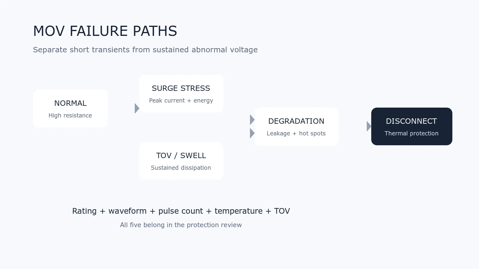
A metal-oxide varistor (MOV) protects a circuit by conducting transient current when voltage rises into its nonlinear region. That useful behavior also means the device absorbs electrical and thermal stress. An MOV is therefore not an unlimited surge sink: its end-of-life behavior must be considered as part of the protection circuit.
This guide explains the main failure paths, the difference between a short surge and a sustained abnormal voltage, and the separate roles of an upstream fuse, a thermally coupled disconnect and a monitoring circuit.
What Can Change Inside an MOV?
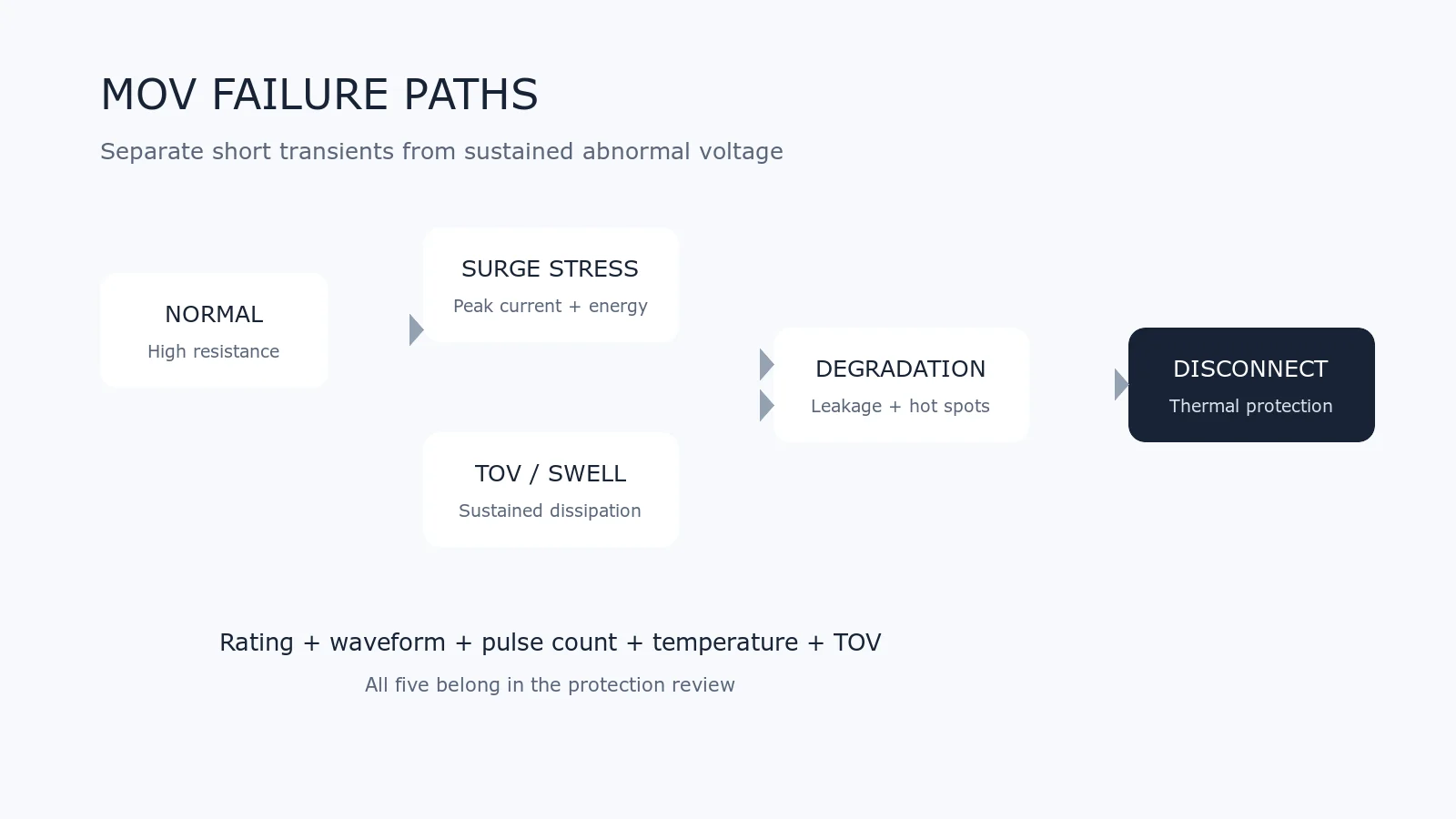
An MOV is made from a nonlinear ceramic body with electrodes and an insulating or molded exterior. Its current-voltage characteristic depends on the ceramic microstructure. Electrical stress that exceeds the device rating, or repeated stress over time, can create localized changes in that structure.
Depending on the device construction and event, observable changes may include:
- higher leakage current at the normal system voltage;
- a shift in varistor voltage;
- lower insulation resistance;
- localized heating or hot spots;
- cracking, coating damage or terminal damage;
- short-circuit or open-circuit behavior after severe failure.
Not every event produces visible damage. A part can look normal while its electrical characteristic has changed. Qualification and reliability work therefore uses electrical measurements and specified pulse sequences rather than visual inspection alone.
Four Important Stress Paths
1. A Surge Above the Single-Pulse Rating
A pulse with excessive peak current or energy can damage the MOV in one event. The rating must be read with its waveform, such as 8/20 microseconds or a specified energy pulse. A current value without the waveform and pulse count is incomplete.
2. Repeated Surges
A single-pulse maximum does not describe unlimited repetition. Repetitive-pulse curves normally reduce the permitted current as the number of pulses increases. Pulse spacing, ambient temperature and the device’s ability to cool also matter.
3. Temporary Overvoltage (TOV) or Voltage Swell
A Temporary Overvoltage (TOV) lasts much longer than a transient surge. If the applied voltage forces sustained conduction, the MOV continuously dissipates power. Heat increases leakage; increased leakage produces more heat. Under unsuitable conditions this positive feedback can develop into thermal runaway.
A surge-current rating does not prove TOV withstand. Mains variation, neutral faults, wiring faults and the applicable system standard must be assessed separately.
4. Excessive Ambient or Nearby Heat
High ambient temperature, insufficient spacing from hot parts and restricted airflow reduce thermal margin. Electrical and mechanical ratings may also require derating at elevated temperature. Use the manufacturer’s temperature curves and installation instructions.
Why a Normal Line Fuse May Not Be Enough
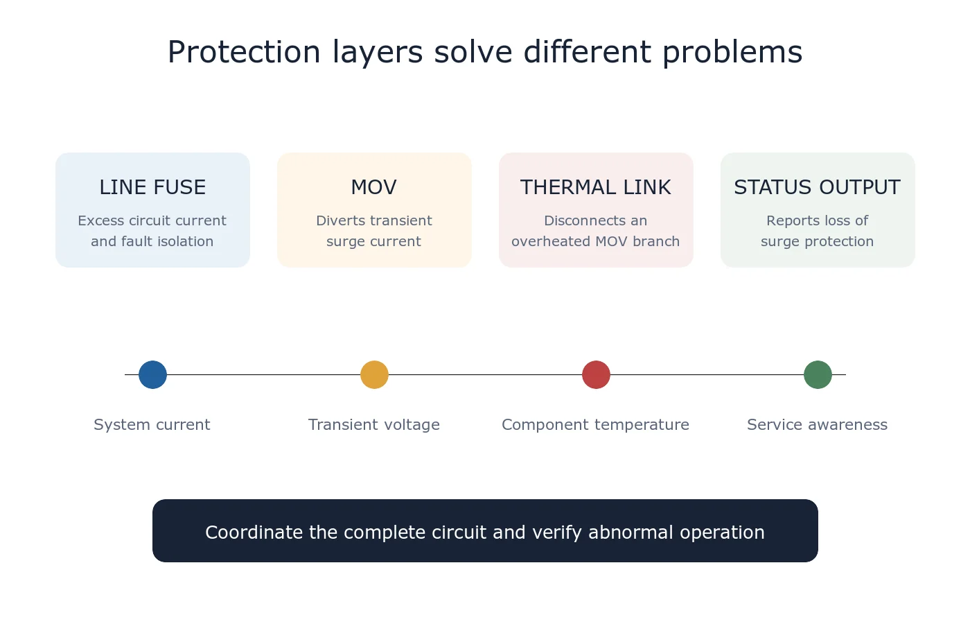
An upstream fuse is essential for many mains-powered products, but its first job is to interrupt excessive circuit current. A degrading MOV may dissipate enough power to become dangerously hot while the current remains below the line fuse’s opening threshold.
This is why “the product already has a fuse” is not a complete MOV end-of-life strategy. The fuse, wiring, MOV, thermal protection and prospective fault current must be reviewed as a coordinated system.
What a Thermal Disconnect Does
A thermally protected MOV places a temperature-sensitive disconnect in series with the varistor and couples it thermally to the MOV body. When abnormal heating reaches the device’s designed trip condition, the disconnect opens the MOV branch.
The disconnect is not a substitute for correct voltage selection or surge sizing. It is an additional safety mechanism for abnormal heating and end-of-life behavior. After it opens, the load may continue to operate without surge protection unless the circuit also removes power or provides an alarm.
Monitoring the Loss of Protection
Some thermally protected parts include a third lead for status monitoring. This can drive an indicator, optocoupler or control input so the equipment can report that transient protection is no longer active.
The monitor circuit must respect isolation, voltage, current and creepage requirements. Treat manufacturer application circuits as starting points and verify the final design for the actual line voltage and safety standard.
Open-Circuit and Short-Circuit Outcomes
Designers should not assume one universal failure state. A severe event can leave an MOV conductive, fragmented or electrically open depending on construction, available fault current, protective coordination and the event itself.
A thermally protected assembly is intended to disconnect the overheated MOV branch. Whether the complete equipment remains energized, gives an alarm or becomes safe but unavailable depends on the surrounding circuit.
Practical Design Checklist
- Select maximum continuous AC or DC voltage with realistic system tolerance.
- Check TOV or voltage-swell behavior separately from surge ratings.
- Compare surge current and energy only under the specified waveform and pulse count.
- Apply temperature and repetitive-pulse derating.
- Coordinate the upstream fuse or breaker with the available fault current.
- Use an appropriate thermal disconnect where the safety analysis requires it.
- Consider a status output when continued operation without protection would be unacceptable.
- Keep the surge-current loop short and physically separate the MOV from heat-sensitive materials.
- Verify enclosure, flame, spacing and abnormal-operation requirements.
- Test the complete assembly; component ratings alone do not certify the equipment.
Frequently Asked Questions
Does every MOV need a thermal fuse?
No single answer applies to every circuit. The need depends on the power source, fault current, safety standard, enclosure, operating voltage, TOV exposure and acceptable failure behavior. Mains-connected designs deserve particular attention.
Can an MOV be reused after a large surge?
Do not decide from appearance alone. If the event approached or exceeded the specified rating, the equipment manufacturer should define inspection or replacement criteria based on electrical measurements and safety requirements.
Is a thermally protected MOV maintenance-free?
No. It improves fault isolation but does not remove the need for correct selection, coordination and system testing. If the thermal element opens, the product may have lost surge protection and should provide a service response where necessary.
Related UBAEC Guides
- Fuse vs MOV Thermal Disconnect: Roles and Coordination
- MOV Protection Circuit Basics
- How to Select an MOV
- MOV Surge Waveforms
- MOV Clamping Voltage
References
- Littelfuse — TMOV and iTMOV Series Datasheet
- TDK Electronics — ThermoFuse Varistors
- Bourns — MOV Behavior During Voltage-Swell Events
For a private review of a circuit or part number, use Ask UBAEC and include the normal voltage, maximum voltage, surge waveform, test level and existing protective devices.












