

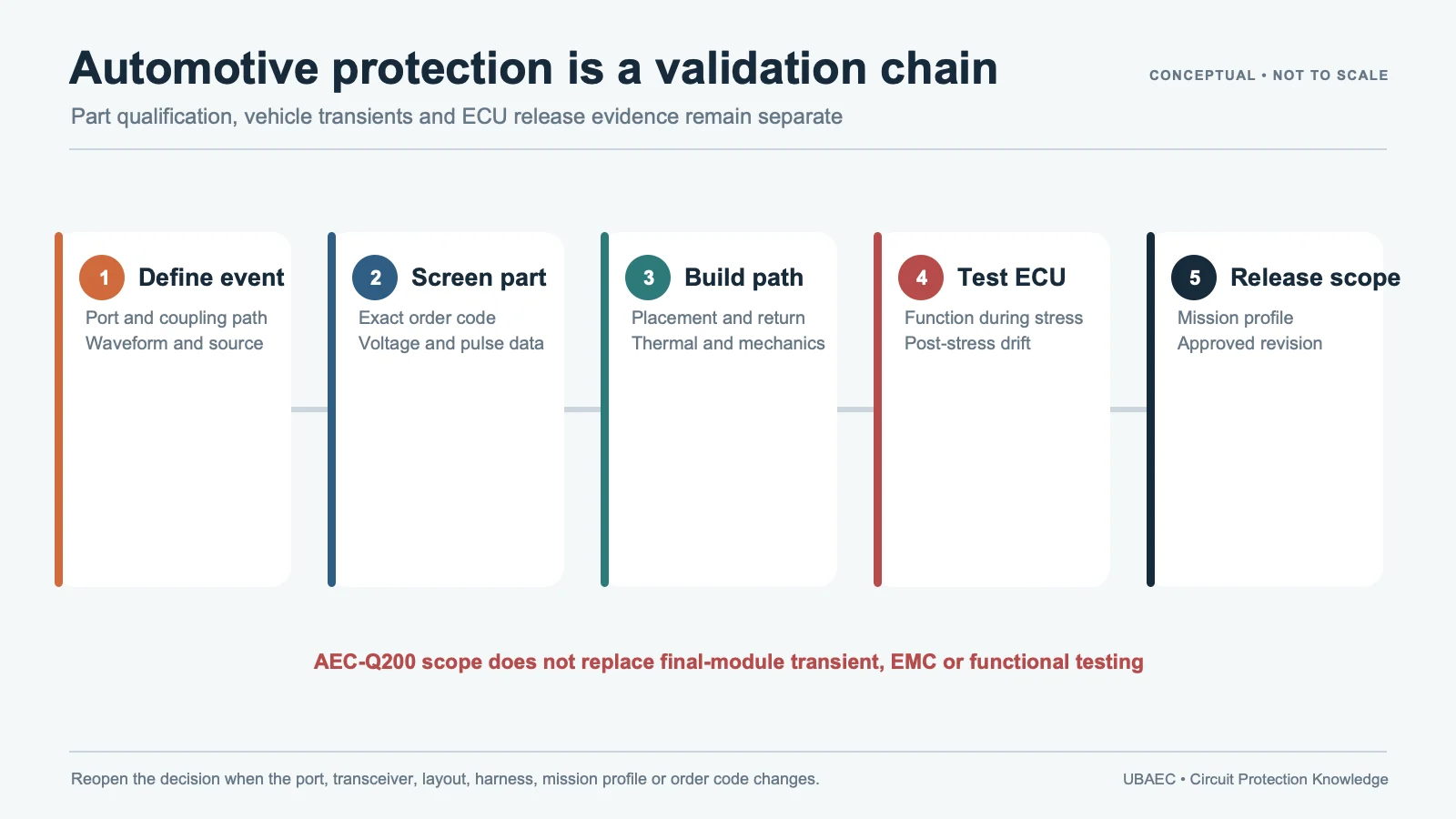
An ECU or sensor module may expose supply, ground, discrete I/O, analog input, CAN/LIN, Ethernet, camera, display, antenna and service connectors on the same housing. These ports do not share one protection requirement. A local MLV is a candidate only after the line’s valid voltage, signal loading, transient source, clamp target, energy, temperature and return path are defined.
Do not combine signal-line and power-line ratings. An MLV with useful energy on a supply rail may load a camera or communication line. A very-low-capacitance ESD part may not absorb a long supply transient. Build a separate requirement and release record for every port class.
Classify the Port Before Choosing a Device
| Port class | Primary checks | Typical coordination |
|---|---|---|
| Supply/local rail | Continuous/abnormal voltage, source impedance, long-pulse energy, repetition, temperature | Fuse/current limit, upstream TVS/MOV, series impedance and local clamp |
| Discrete/analog/sensor | Threshold or accuracy, leakage, capacitance, bias, coupled transients and input protection | Series resistor/filter, shielding, local MLV/TVS and controlled reference |
| CAN/LIN or similar bus | Common-mode range, topology, balance, waveform and exact interface evidence | Choke/termination, matched or single-line protector and transceiver protection |
| Ethernet/camera/display/RF | Data rate or band, S-parameters, differential balance, matching and dynamic clamp | Very-low-capacitance technology, common-mode/filter network and shield |
Use the parameter and test-condition guide. Retain VDC/VAC, varistor-voltage test current, Vc current and waveform, energy duration, peak-current waveform, capacitance frequency/bias, leakage and temperature. Missing values remain unknown; they are not borrowed from a neighboring part.
Read Application Lists as Discovery, Not Approval
KYOCERA AVX’s automotive hub covers communication bus, controlled-capacitance, antenna, high-temperature, TransGuard and TransFeed families. The hub establishes portfolio scope but directs selection to series and exact-part documentation. Panasonic’s automotive sell sheet shows ECU, sensor and I/O examples and specific EZJP tables; footprint, weight and temperature statements remain tied to those comparisons.
Eaton AMLV documentation includes ECU, CAN, LIN, FlexRay, ADAS, LED and motor applications with part-specific Vjump, load-dump, capacitance and clamping fields. Do not combine the strongest value from each row. Bourns CGA-MLA documentation lists camera, sensor, Ethernet and touchscreen applications, but the current PDF also says the series is available yet not recommended for new designs and points to BVRA replacements. A legacy application list is not a new-design recommendation.
Separate the Transient Sources
ISO 10605:2023 covers automotive module and vehicle ESD methods. ISO 7637-2:2011 covers conducted transients on supply lines for 12 V and 24 V systems. ISO 7637-3:2016 covers transients coupled to non-supply lines using defined coupling methods. All three remain current on the official records, but they address different test objects and phenomena.
An 8/20 µs peak-current rating, 10/1000 µs energy value, ISO 10605 ESD result and ISO 7637 pulse are not interchangeable. Use the local-rail guide for supply paths. Route CAN/CAN FD, LIN/CXPI and Automotive Ethernet through their dedicated CAN/CAN FD, LIN/CXPI and Automotive Ethernet/RF methods.
Design the Current Return and Protection Stages
Place a local suppressor near the connector or entry point only after choosing its return: shield/chassis, module ground or another controlled reference. Review harness, connector, ground offset, isolation, series impedance, common-mode filter, input capacitor, upstream clamp and protected IC together. A short trace that injects current into an analog reference can still be a bad layout.
TDK’s ESD-visualization work shows that mounting location changes the current path under a defined evaluation setup. Apply the principle with the layout and mounting guide; do not turn one board’s distance result into a universal placement dimension.
Validate the Final Module
- Record exact module/PCB/firmware revision, cable, enclosure, shield and grounding.
- Verify order code, lifecycle, qualification, temperature and all electrical test conditions.
- Measure loading, signal integrity or sensor accuracy before transient testing.
- Run ISO/customer ESD, coupled-line and supply-line tests separately.
- Measure current through the protector and voltage at the protected node.
- Check function, communication, leakage, Vvar/clamp drift, temperature and physical condition after stress.
- Repeat tests after alternates, layout, harness, shield, filter or upstream-stage changes.
AEC-Q200 is component qualification, not ECU or vehicle compliance. Use the reliability and standards guide and the MLV selection workflow to preserve the evidence chain.
Minimum Inquiry Data
- port class, normal/common-mode/fault voltage and protected-device limit;
- bandwidth/data rate, leakage/capacitance budget and source/load impedance;
- ESD, coupled transient and supply-pulse generators, repetition and acceptance;
- harness, connector, shield, grounding, isolation and coordinated components;
- temperature, package, qualification, lifecycle and exact order code.
Control Lifecycle and Alternate Parts
A protection part can remain orderable while being unsuitable for a new design. Record active, NRND and replacement status separately, and verify the replacement datasheet rather than assuming the supplier’s suggested series is electrically identical. The Bourns CGA-MLA notice is a concrete reason to keep lifecycle inside the engineering gate.
For every alternate, compare construction, topology, package, termination, VDC, Vvar test current, Vc/current, pulse/energy conditions, capacitance/leakage, temperature, qualification and layout. Then repeat the affected signal, transient, thermal and fault tests. Approval belongs to the exact part plus module revision, not to a family name.
Summary
Protect automotive module I/O by classifying each port and keeping signal, power and transient evidence separate. Release only the exact device and topology that pass the final module’s functional, EMC, thermal and post-stress checks.
Use the MLV Technical Resources & Datasheet Library or return to the MLV Knowledge Map.
Continue Reading
- Automotive Ethernet and RF-Adjacent ESD Protection with MLVs
- CAN and CAN FD Protection with Multi-Element MLVs
- MLV PCB Layout, Mounting and Soldering Reliability
- How to Select an MLV: A Practical Engineering Workflow
Official Technical References
The following first-party, standards-organization or publisher records support the technical boundaries used in this article. Always verify the current revision and the exact product scope before design release.
- KYOCERA AVX automotive circuit protection portfolio
- Automotive chip varistor sell sheet
- AMLV automotive grade multilayer varistor datasheet
- ChipGuard Automotive MLA Series Varistor ESD Clamp Protectors datasheet
- ISO 7637-2:2011 – Road vehicles – Electrical disturbances from conduction and coupling – Part 2: Electrical transient conduction along supply lines only
- PCB Layout for ESD Countermeasures: ESD Visualization











