

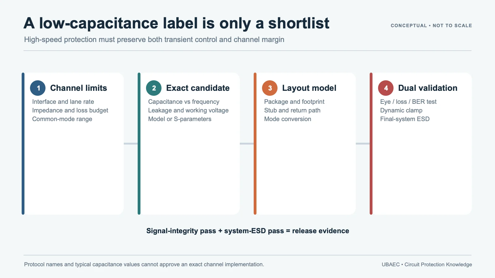
Automotive Ethernet and RF-adjacent lines combine two difficult requirements: the protector must divert a fast ESD event while remaining almost invisible to the wanted signal. “Low capacitance” is only the start. Protocol, topology, tolerance, frequency response, mode conversion, dynamic clamp, working voltage, qualification, package and PCB return path all belong to the decision.
Do not transfer one interface claim to another. Evidence for 10BASE-T1S does not automatically cover 100BASE-T1, 1000BASE-T1 or Multi-Gigabit Ethernet. An antenna or radar line is not validated by an Ethernet label, even when the same product family mentions both applications.
Separate the Interfaces Before Comparing Protectors
| Interface | Electrical questions | Release evidence |
|---|---|---|
| 10BASE-T1S | Multidrop/P2P topology, node count, branch length, line-to-line capacitance, balance and mode conversion | Exact OPEN Alliance scope plus full network signal/EMC test |
| 100/1000BASE-T1 | Data rate, differential impedance, common-mode network, insertion/return loss and transceiver limits | Exact order-code mapping and link/eye/S-parameter validation |
| Antenna/RF/radar adjacent | Frequency band, source/load impedance, matching, noise, leakage, bias and allowable detuning | Measured S-parameters or RF performance in the actual network |
Use the parameter and test-condition guide. A capacitance value needs frequency, amplitude, DC bias, tolerance and typical/maximum basis. A surge clamping voltage and an ESD dynamic waveform are different measurements. Insertion loss is fixture-, topology-, frequency- and order-code-specific.
What Current First-Party Evidence Actually Shows
TDK’s March 2025 10BASE-T1S application note maps named AVRH chip varistors to the OPEN Alliance 10BASE-T1S ESD-component framework and publishes line-to-line capacitance and S-parameter context. That is strong direct evidence for the listed parts and topology; it is not a blanket AVRH or Automotive Ethernet approval.
KYOCERA AVX ASPGuard Rev 1 names one VCAS04AP order code for 1000BASE-T1 and another for 100BASE-T1, and separately presents RF, sensor, antenna and radar use. The same document attaches working voltage, breakdown, clamp current, 8/20 µs peak current, 10/1000 µs energy and 1 MHz/0.5 VRMS capacitance conditions to exact rows. Its portfolio ranges cannot be combined into a fictional universal part.
Littelfuse’s connectivity guide is useful for architecture: it separates varistors, TVS arrays, fuses and other technologies across cameras, V2X, infotainment, radar and power functions. It also requires users to evaluate exact products in their own systems. Treat the diagram as role discovery, not an interface qualification.
Build the Signal-Integrity Budget
Before selecting a protector, record protocol and data rate, topology, harness and connector, differential/common-mode impedance, transceiver limits, termination, common-mode choke, expected PCB parasitics and the remaining capacitance budget. For RF-adjacent lines, add operating band, matching network, antenna or sensor impedance, acceptable return loss, noise and power-handling limits.
Do not rank MLV and diode options by one capacitance number. Use the MLV versus TVS comparison and the high-speed port method to compare exact candidates under matched conditions. Low capacitance can improve loading but can also be paired with a higher residual voltage; the outcome depends on the complete device and setup.
Control the ESD Current Path
Place the candidate near the connector or defined entry point, with a short shunt path to the intended return. Coordinate shield/chassis strategy, common-mode choke, termination, filtering, ESD array or other suppressor and transceiver internal protection. A short physical distance alone is not enough if current is returned through a sensitive circuit reference.
Follow the layout and mounting guide. If the network contains CAN or LIN segments, keep their evidence separate through the CAN/CAN FD guide and LIN/CXPI guide. For broader ECU, sensor and camera-port routing, use the automotive module I/O guide. Non-automotive audio, antenna and RF-adjacent nodes require their own application review; that guide is not linked until its editorial review is complete.
Validate the Exact Interface and Order Code
- Verify lifecycle, package, termination, qualification and exact protocol claim.
- Measure capacitance and S-parameters with the intended fixture, bias and layout.
- Run link, eye/jitter or RF matching/noise tests across temperature and tolerance.
- Apply ISO 10605 and customer ESD setups with documented polarity, coupling and acceptance.
- Measure protector current and protected-node voltage during the event.
- Repeat functional and signal tests after stress; inspect leakage, drift and physical condition.
AEC-Q200 and an OPEN Alliance statement apply only to the named order code and cited scope. They do not establish ECU, link or vehicle compliance. Use the reliability and standards guide and the MLV selection workflow for the release record.
Minimum Inquiry Data
- interface, data rate/band, topology, node count, harness and connector;
- differential/common-mode impedance, termination, choke/filter and transceiver limits;
- capacitance tolerance, S-parameter/eye/RF budget, leakage and bias;
- ESD generator, coupling, polarity, repetition and acceptance criteria;
- temperature, package, qualification, exact order code and PCB return path.
Reopen the Decision When the Network Changes
A protection decision is tied to one interface and one physical implementation. Reopen it when the data rate, topology, transceiver, common-mode choke, connector, harness, branch length, termination, PCB stack-up, ESD return, enclosure or order code changes. For RF-adjacent paths, a matching-network or antenna change also reopens the decision.
An alternate part must pass the same capacitance-tolerance, S-parameter, working-voltage, dynamic-clamp, qualification and lifecycle gates. A distributor cross-reference, similar family name or equal nominal capacitance cannot establish interchangeability. Record the tested module revision and retain the measurement files with the approval.
Summary
An MLV can be a candidate for automotive Ethernet or RF-adjacent ESD protection only when the exact interface, order code and measured signal path agree. Protocol names and “low capacitance” labels are not transferable guarantees.
Use the MLV Technical Resources & Datasheet Library or return to the MLV Knowledge Map.
Continue Reading
- High-Speed Port ESD Protection: MLV, TVS and Low-Capacitance Trade-Offs
- MLV vs Resin and Polymer ESD Suppressors
- MLV PCB Layout, Mounting and Soldering Reliability
- MLV Arrays, Multi-Element Devices and Feedthrough Filters
Official Technical References
The following first-party, standards-organization or publisher records support the technical boundaries used in this article. Always verify the current revision and the exact product scope before design release.
- Common Mode Chokes and Chip Varistors for 10BASE-T1S
- ASPGuard low-capacitance varistors datasheet
- Connectivity and Autonomous Driving Solutions Spotlight
- ISO 10605:2023 – Road vehicles – Test methods for electrical disturbances from electrostatic discharge
- Multilayer varistors (MLVs) High-speed series datasheet











